
WAYON TOLL package power MOSFET is the most ideal package for high-current application scenarios. Its product series can reach a maximum current of 300A or more, mainly used in similar power BMS, inverter energy storage, low-speed electric vehicles, power tools, UAV ESC, submersible motors and other high-current application scenarios.
The TOLL package occupies only 9.90 mm x 11.68 mm, saving 30% of PCB area compared to the TO-263-7L package. With a profile of only 2.30 mm, it occupies 60% less volume than the TO-263-7L package.
In addition to its smaller size, the TOLL package offers better thermal performance and lower package inductance (2nH) than the TO-263-7 lead. Its Kelvin source configuration ensures lower gate noise and switching losses, including a 60% reduction in turn-on loss (EON) compared to device without a Kelvin configuration, ensuring significantly higher energy efficiency and power density, improving electromagnetic interference (EMI) and easier PCB design in challenging power supply designs.
TOLL package product features:
● Small pins, low profile
● Super high through-current capability
● Ultra-small parasitic inductance
● Large soldering area
TOLL package product advantages:
● High efficiency and low system cost
● Less number of parallel connections and cooling requirements
● High power density
● Excellent EMI performance
● High reliability
TOLL and TO-263-7L Appearance Comparison


30% footprint reduction !
50% height reduction !
60% space reduction !
Comparison of Parasitic Parameters between TOLL and TO-263-7L

WAYON TOLL Package Mass Production Product Line

WAYON TOLL Package Product Planning

电压:Voltage
量产供货: Mass production supply
计划中:On Schedule
Introduction of the advantages of the WAYON TOLL package products
Higher power density
The rapid development of new energy products (new energy vehicles, energy storage and supporting applications) and high-power power supplies and motors has further increased the requirements for energy efficiency. MOS tubes need to withstand instantaneous high energy flow, and achieve the highest heat dissipation rate and lowest thermal resistance within the physical heat dissipation limit of the material. In this condition. The TOLL package with ultra-low on-state impedance and parasitic inductance, as well as better EMI performance and thermal performance can meet the requirements of this development trend. In addition, the TOLL package requires fewer parallel and thermal components in the actual circuit design application, which can save PCB space and thus improve the overall reliability.
Low Temperature Rise
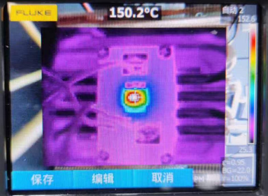
In BMS applications, the temperature performance of MOSFETs is critical to the overall efficiency and temperature of the system when subjected to continuous high current charging and discharging. The TOLL package product WMLL020N10HGS (BVdss 100V, Rdson 2mR max) has passed the continuous 40A overcurrent capability test at 26°C ambient temperature:
Heat dissipation through the PCB with a temperature rise of only 61°C;
The temperature rise is only 32℃ through aluminum substrate heat dissipation.

PCB Heat Dissipation

Aluminum Substrate Heat Dissipation
High short-circuit tolerance
In BMS and motor control applications, MOSFETs are subjected to high current shocks ranging from tens of uS to hundreds of mS at the moment of short circuit, with transient power up to hundreds of KW. The laboratory simulations of the power performance of the TOLL package WMLL020N10HGS (BVdss 100V, Rdson 2mR max) in the event of an overlapping short circuit in a motor rotating at high speed:

Oscilloscope waveform 1CH: Vgs 2CH: Vds 4CH: Ids M1: MOS power consumption
Single short circuit, VDD=88V Short circuit maximum current 1550A, maximum power dissipation 101.5KW
Robust Continuous Linear Mode of Operation
In linear mode, the MOSFET operates in the saturation state or saturation region and behaves as a current source controlled by the gate voltage. In contrast to the fully conduction (or fully enhancement) case, MOSFETs in linear mode have relatively high drain-source impedance and thus higher power consumption. In linear mode, the power is equal to the product of drain current and drain-source voltage (ID × VDS), both of which have relatively high values. Laboratory simulations of the TOLL package product WMLL020N10HGS (BVdss 100V, Rdson 2mR max) in near DC operation at long pulse times to test MOSFET linear mode robustness, the product’s power capability under linear mode operating conditions, are within the theoretical safe operating area (SOA), preventing any thermal runaway of the device.

VDS=28V Ids=2.5A Linear mode 70W dissipated power continuous operation
Super motor heavy-duty drive capability
3000W high-power 72V motor system has a very high demand on the load capacity of MOSFETs. Laboratory simulation of the TOLL package product WMLL020N10HGS (BVdss 100V, Rdson 2mR max), uses a six-tube bridge arm MOSFET drive, the upper and lower two are cross-conducted. One tube stays on during conduction, one tube is PWM modulation signal. The output current level will be adjusted according to the PWM duty cycle.

Pulling inductive loads, oscilloscope waveform 1CH: upper bridge arm Vgs 2CH: upper bridge arm Vds
6 MOS pull load 72V 42A, 3000W DC brushless motor load

Oscilloscope waveform 1CH: Vgs 2CH: Vds 4CH: Ids M1: MOS power consumption
The upper bridge arm MOS can withstand 103V, 1300A instantaneous power surge